fiber distributed data interface II (FDDI II)
The standard FDDI supports asynchronous and synchronous services. Due to the isochronous services not provided for in the standard, it is not possible to transmit multimedia services, i.e. moving images or voice. This gap is closed by FDDI-II, the definition of which began in 1984. The FDDI-II standard is upwardly compatible with FDDI (FDDI-I). In addition, a CS(Circuit Switch) service was defined, which enables isochronous transmission.
Synchronization of the ring is now no longer distributed, i.e. possible between two adjacent stations in each case, but requires a central station, the cycle master. The transmission bandwidth of 100 Mbit/s is subdivided into 16 wideband channels (WBC) with a transmission capacity of 6.144 Mbit/s. Each wideband channel consists of a 96 channel unit. Each wideband channel consists of a 96- byte sequence that is transmitted 8000 times per second, i.e. at intervals of 125 microseconds. One byte thus corresponds to a transmission channel of 64 kbit/s of transmission bandwidth for the smallest possible isochronous channel of FDDI II.
Each network station can reserve n x 64 kbit/s of bandwidth to transmit isochronous data. Nevertheless, reserved channels can also be used to transmit asynchronous data. Thus, multiple virtual FDDI rings can be configured within one FDDI II ring.
The structuring of FDDI II
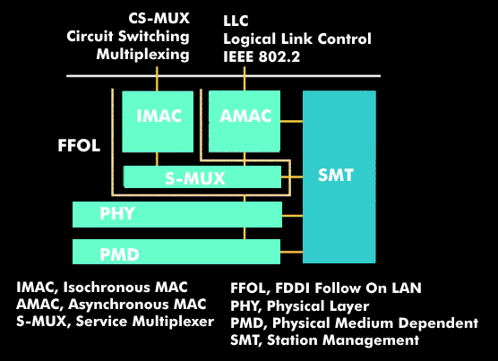
The structuring of FDDI-II as well as FDDI corresponds to the OSI reference model and includes the definition of the two lowest layers, the physical layer and the MAC sublayer. The lowest sublayer of the physical layer, the PMD layer, is adopted unchanged. Changes have been made in the upper sublayer based on this, the PHY layer, in which, among other things, the 4B5B coding is performed.
Another symbol has been introduced for the detection of the HRC(Hybrid Ring Control) frame. In FDDI-II, the start delimiter is formed by symbols I and L, while symbols J and K define the start of the HRC frame. This instance HRC forms the main innovation in FDDI-II. HRC is formed by the H-MUX (Hybrid Multiplexer) and I-MAC (Isochronous MAC) entities. HRC is responsible for handling the entire mechanism that enables isochronous data traffic. For this purpose, it identifies the current operating mode and further monitors the function of the HRC frame.