Structure chart
The notation of the structure diagrams is based on a proposal by Nassi and Shneiderman from 1973, and allows the graphical representation of control structures as well as the technique of a program flow chart. Control structures are used to control the flow of an algorithm. The notation is standardized in DIN 66261.
Structure diagrams according to Nassi and Shneiderman represent each elementary structure block of structured programming as a clearly recognizable graphic individual symbol. There are clear rules for the representation of a sequence, a selection and a repetition. For practical reasons special forms like counting loop and multiple selection are defined as additional structure blocks.
By the renunciation of arrows for the representation of the control flow a considerably clearer representation of algorithms is possible than with a program flow chart. The constraint to divide the graphical representation area leads to the decomposition of the algorithm into sub-algorithms. Structure diagrams thus support the refinement technique in the planning of software systems. These offer substantially more representation area for explanations and increase thus the readability.
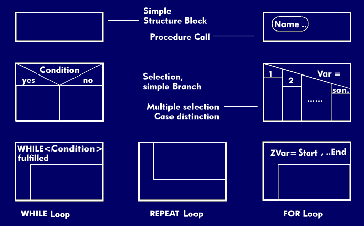
All the elementary structure blocks shown in the figure can be put together in a simple way. The result is again a manageable structure block with exactly one input and exactly one output.
For the construction of composite structure blocks there are two simple rules following the block concept:
- One structural block is lined up with another by merging the entire output edge of the preceding structural block with the entire input edge of the succeeding structural block. A structural block created by such a series is called a sequence.
- Any elementary or composite structural block can then be inserted intothe block fields of the elementary structural blocks to cover the edges.