optical time domain reflectometry (wiring) (OTDR)
Optical time domain reflectometry (OTDR) is a method for measuring and testing optical fibers. The OTDR method can be used to directly detect faults in FO cables, but also to measure and analyze transmission-related parameters. The measurement on classic coaxial cables and TP cables is carried out with time domain reflectometry(TDR) devices.
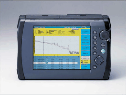
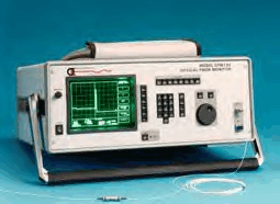
In OTDR measurements, a light pulse from the source of the OTDR device is injected into the optical fiber. This light pulse is reflected within the optical fiber by backscattering, but especially at cable breaks, at splices, FO connectors and adapters, and returns to the OTDR instrument where it is measured and evaluated. The propagation time of the reflected light pulse can be used to directly infer the location of the fault. Conclusions about the type of fault can be drawn from the attenuation curve of the pulse.
Since optical fibers exhibit attenuation due to backscattering and absorption, the level attenuation of the light pulse is the direct measure of the attenuation of the optical fiber. A higher level attenuation occurs at splices, while a higher reflection occurs at notches or faulty connectors, resulting in an increase of the reflected light level.
Highly accurate fault location with OTDR measurement
The energy of the light pulse and its pulse width determine the temporal and level resolution capabilities. Light pulses with larger pulse widths have lower temporal resolving power compared to those with narrow pulse widths; however, they have better level resolution. For a light pulse width of one microsecond, a spatial resolution of 100 meters can be assumed. Thus, with a pulse width of 1 ns, a resolution of 10 cm is achieved, with a pulse width of 100 ns, a resolution of 10 m is achieved, and with a pulse width of 10 microseconds, a resolution of 1 km is achieved. The level resolution is improved by about 5 dB per decade in each case due to the higher energy of wider pulses: that is, a light pulse of 100 ns has a level resolution 5 dB better than a pulse with a width of 10 ns.
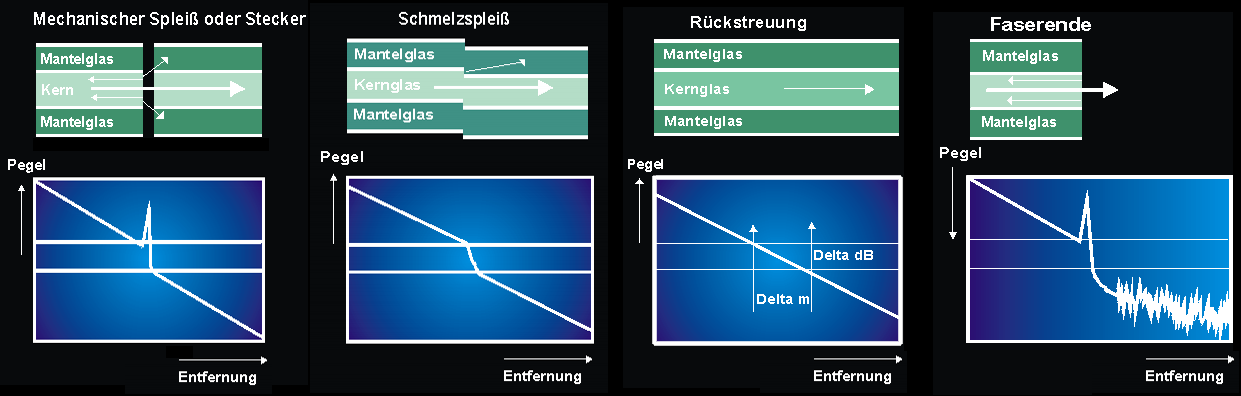
Typical fiber links are characterized by a wide variety of impairments that significantly affect the transmission behavior. These impairments cause backscatter and additional attenuation. The various splice connections, the fusion splice, the adhesive splice and the crimp splice, FOC plug connections and, in addition, the direct impairments of the fiber itself, due to strong bends, breaks or cracks, are to be mentioned. Each of the mentioned impairments has its own typical reflection characteristic and can therefore be directly detected and analyzed in the OTDR measurement.
Defect analysis with OTDR measurement
If a homogeneous fiber is analyzed with the OTDR measurement, it is characterized by a constant backscatter. Depending on the fiber type - monomode fiber or multimode fiber - this backscatter is smaller or larger and is a direct measure of the attenuation over a certain distance. In the OTDR plot, where the level or attenuation is plotted on the vertical and the horizontal represents the distance axis, a falling line is shown. Where the ratio of vertical parts (delta dB) to the corresponding horizontal part (delta m) corresponds to the attenuation of the fiber.
A fusion splice will cause increased attenuation, as will severe fiber bending. The OTDR plot will take a dive.
Mechanical splices or FOC connectors with an air gap, just like a fiber break first cause increased reflection before the increased attenuation occurs. The plot typically shows a spike up followed by the jump down. At the fiber end, which may be smoothed or broken, the light beam is reflected in the first case, and in the second case it enters the air medium without reflections. The smoothed fiber end shows a positive peak followed by noise. For the refracted fiber end, no reflection occurs, the end is indicated by the attenuation jump followed by noise.