inter integrated circuit bus (I2C)
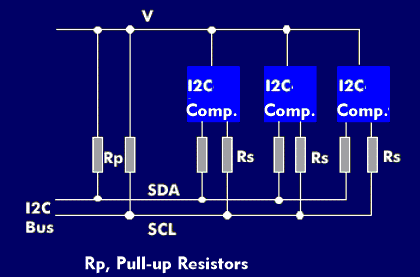
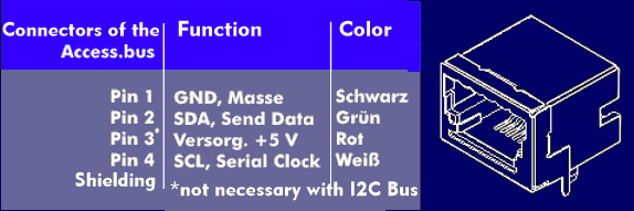
The Inter-IC bus, usually referred to as the I2C (I square C) bus, is a control bus for communication between integrated circuits (IC) of a system. It was conceived by Philips in the 1980s and has become a de facto standard for system control. It is a low-cost, low- data-rate, bi-directional, 2- wire bus whose two wires carry the clock signal, Serial Clock Line (SCL), and the data signal, Serial Data( SDA).
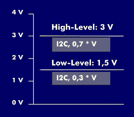
Both lines are biased via pull-up resistors as AND gates. The switching levels depend on the supply voltage; the Hi level is below 3 V and corresponds to 0.7 x supply voltage, the Lo level is below 1.5 V and is 0.3 x supply voltage.
The clock frequency is 100 kHz as standard, in two higher clocked versions 400 kHz and 2 MHz
I2C bus in master-slave mode
With the I2C bus designed for master- slave operation, which is essentially the same as the System Management Bus( SMBus), all I2C components can be connected directly; likewise, each I2C master can assume the switching function to the I2C slaves. Several masters and I2C components with different data transfer rates can also be connected to the I2C bus. If, for example, an I2C slave operates more slowly than the transmitting I2C master, then the latter receives a signal from the slave to reduce the data transfer rate, which it adjusts accordingly. However, only one I2C master can communicate with an I2C slave in half- duplex. Due to the software based addressing scheme no hardware for address decoding is required. The slaves are addressed with 7 bits by default and with 10 bits for extended address space.
In the 20 years the I2C bus has been continuously developed and knows three data transfer modes: In standard mode, the data transfer rate is 100 kbit/s, in fast mode, it reaches up to 400 kbit/s, and in high-speed mode, it reaches up to 3.4 Mbit/s. In addition, the bus hubs, repeaters, bidirectional switches and multiplexers significantly expand the original number of connectable components. In this context, software-controlled collision detection and arbitration should also be mentioned, which ensure high availability and performance even in complex systems.
Areas of application of the I2C bus
The I2C bus can be used in many different ways. For example, for the control and monitoring of sensors to Electrically Erasable PROM( EEPROM), from universal I/Os, to A/D converters, D/A converters, amplifiers, oscillators and clock generators, to codecs and microprocessors. Typical applications are in consumer electronics devices, where it provides for the communication of integrated circuits (IC) with each other. For example, in television sets, camera modules and video recorders, DVD players and cell phones.
Since the I2C bus no longer meets the requirements of the more complex processors and system-on-chips( SoC), the MIPI alliance, Mobile Industry Processor Interface, is attempting to replace it with the SPMI interface, System Power Management Interface.