LAN reference model (LAN/RM)
To integrate different technologies into a uniform interface definition, the OSI reference model for LAN applications was modified slightly and the LAN layer model was derived from it. This model is modified by the working groups according to the respective requirements
The subdivision of the LAN layer model
In the LAN layer model, the link layer is divided into two sublayers and the physical layer into three sublayers in the 10 Mbit/s variants according to 802.3.
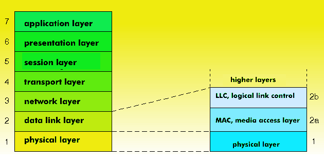
The data link layer consists of the medium access control( MAC) and the logical link control( LLC) sublayer. The latter provides a uniform interface at the top for all systems for setting up logical connections. Access methods such as Token Ring, Token Bus, CSMA/ CD or Distributed Queue Dual Bus( DQDB) reside on the MAC sublayer.
The Logical Link Control services are described by the subscriber interface, which is also often referred to as the DLC manager(Data Link Control Manager). The DLC manager is an important component of the LAN data link layer.
The physical layer experiences a three-way division in 802.3: Physical Layer Signalling( PLS), Access Unit Interface( AUI), and Medium Attachment Unit( MAU), which allows encodings, drop cables, voltages, frequencies, data connectors, etc. to be systematically qualified.
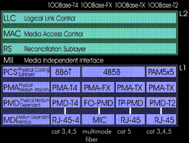
Three- and four-part LLC layer for high-speed variants
For Fast Ethernet with 100Base-T and 100Base-X, the link layer is divided into three parts: Logical Link Control (LLC), Media Access Control (MAC) and Reconciliation sublayer( RS). In this layered architecture, a media-independent interface, the Media Independent Interface( MII), is located between the link layer and the physical layer, providing a uniform interface to the physical layer.
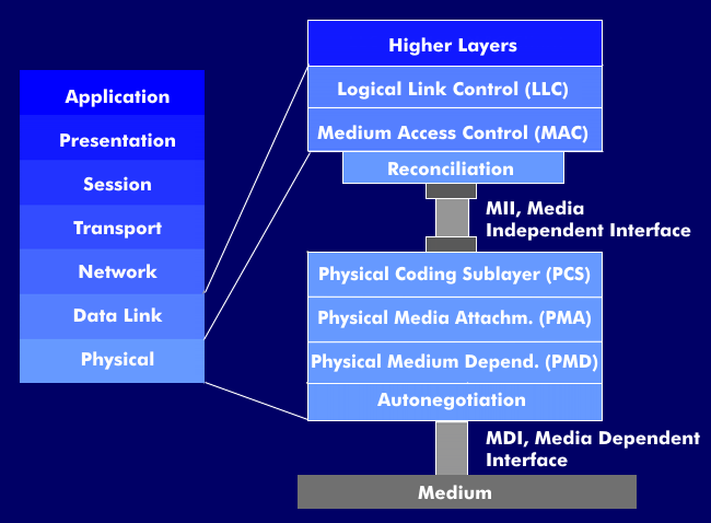
In the 100 Mbit/s variants, the physical layer is divided into four parts: physical coding sublayer( PCS), physical media attachment( PMA), physical media dependent( PMD) and autonegotiation sublayer for autonegotiation( ANP).
The layer model of Gigabit Ethernet largely corresponds to that of Fast Ethernet. The data link layer is further subdivided into the MAC Control sublayer. The physical layer has four columns, corresponding to the different media accesses for multimode fiber, monomode fiber, STP and UTP cable.
The MAC control sublayer is also part of the 10 Gigabit Ethernet layer model, which corresponds in the link layer to the Gigabit Ethernet layer model. In contrast to this, however, some layers and interfaces have been redefined for 10GbE.
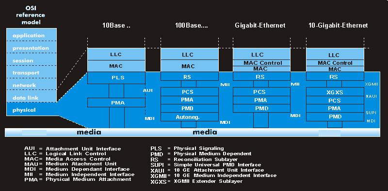
XGMII, the 10 Gigabit Media Independent Interface, serves as the interface between the MAC and the Physical Coding Sublayer (PCS) or XGMII Extender Sublayer (XGXS). The XAUI interface, 10 Gigabit Attachment Unit Interface, serves as the interface between two XGXS units. Another component of 10 Gigabit Ethernet is the WAN Interface Sublayer (WIS).